TM-9-2320-361-24-1 - Page 1144 of 1176
TM 9-2320-361-24-1
0186 00
0186 00-6
WHEEL, TIRE, AND TUBE MAINTENANCE (Contd)
WHEEL INSTALLATION
CAUTION
When installing stud nuts, ensure to put the curved (ball seat)
surface of the nut toward the wheel to seat properly. Failure to
do this may result in damage to wheel.
NOTE
• Wear of rear dual tires should be matched as closely as
possible. Valves on rear tires must be opposite each other
(180° apart).
• Ventilation holes in outer wheel should be directly aligned
with ventilation holes in inner wheel.
• Nuts have left-hand threads on left wheel assembly and right
and threads on right wheel assembly. Studs and nuts are
stamped (L) left and (R) right.
• Assistant will help steps 1 and 3.
• If inner-rear wheel is being replaced, ensure inner stud nuts
are properly seated when installed.
• If inner-rear wheel is being installed, perform step 4. If outer-
rear wheel or front wheel is being installed, go to step 5.
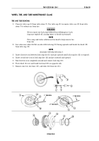
1.
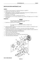
Lift inner wheel (4) and install on wheel studs (3).
2.
Install and hand tighten six wheel capnuts (2) on wheel studs (3).
3.
Tighten six wheel capnuts (2) in tightening sequence shown 400–425 lb-ft (542–576 N
•
m).
4.
Lift wheel (1) and install on wheel capnuts (2) with six stud nuts (5). On front wheel, ensure brake
inspection plate (6) is visible through ventilation hole.
5.
Install and hand-tighten six new wheel cap nuts (5).
6.
Tighten six stud nuts (5) in sequence shown on front wheel 325–355 lb-ft (441–481 N
•
m) and six
stud nuts (5) on wheel (1) 325–355 lb-ft (441–481 N
•
m).
7.
Raise vehicle with hydraulic jack, remove jack stand, and lower vehicle to ground.
8.
Connect battery ground cable (WP 0126 00).
9.
Release parking brake and remove wheel chocks (TM 9-2320-361-10).
END OF WORK PACKAGE
5
1
2
3
4
5
~
6
TIGHTENING
SEQUENCE
1
3
5
2
4
6
JACK
STAND
Back to Top


