TM-9-2320-361-24-1 - Page 238 of 1176
TM 9-2320-361-24-1
0014 00
0014 00-2
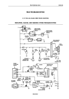
INDICATORS, GAUGES, AND WARNING SYSTEM TROUBLESHOOTING (Contd)
MALFUNCTION
TEST OR INSPECTION
CORRECTIVE ACTION
1. ALL GAUGES
INOPERATIVE
NOTE
If STE/ICE-R is available, perform
NG31 gauge test (WP 0018 00).
Test 1. Test starter for proper
operation.
1. Turn power accessory switch
to ON position.
2. Turn start button.
Test 2. If problem is still present, test
instrument cluster voltage.
1. Turn power accessory switch
to OFF position.
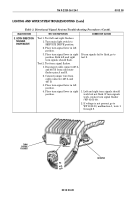
2. Remove instrument cluster
panel (WP 0093 00).
3. Verify battery ground cable is
connected (WP 0126 00).
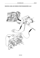
4. Connect jumper wire from
instrument panel to good
frame ground.
5. Disconnect lead 27 from
temperature gauge.
6. Use multimeter or 24 volt test
lamp to check voltage on
contact end of lead 27 at
gauge.
7. Place positive lead on contact
end of lead 27.
8. Place negative lead on frame
ground.
9. If battery voltage is present,
go to WP 0014 00, table 1,
malfunction 2.
10. Set multimeter to RX 1 scale.
11. Check continuity of lead 27.
12. Disconnect lead 27 from front
wiring harness.
Verify that proper voltage is present.
1. If starter cranks engine, go to
test 2.
2. If starter does not crank engine go
to WP 0012 00, table 2,
malfunction 1 and troubleshoot
starter circuit.
If continuity is not present, repair or
replace lead 27 (WP 0090 00).
Table 1. Indicator, Gauges, and Warning System Troubleshooting.
Back to Top

