TM-9-2320-361-24-1 - Page 818 of 1176
TM 9-2320-361-24-1
0118 00
0118 00-2
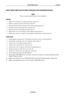
FRONT WHEEL DRIVE LOCK-IN SWITCH INDICATOR AND AIR PRESSURE SWITCH
NOTE
Prior to removal, tag all lead wires for installation.
REMOVAL
1.
Remove wire connector (11) from air pressure switch (10).
2.
Remove air pressure switch (10) from air valve (9).
3.
Disconnect wire (15) from connector (16) at front wiring harness (1).
4.
Disconnect wires (12) and (13) from connector (14).
5.
Disconnect wire (8) from indicator lamp socket (7).
6.
Remove lens cover (4) and lamp (3) from indicator lamp socket (7).
7.
Remove two screws (5), washers (6), and indicator lamp socket (7) from bracket (2).
INSTALLATION
1.
Install indicator lamp socket (7) on bracket (2) with two screws (5) and washers (6).
2.
Install lamp (3) and lens cover (4) on indicator lamp socket (7).
3.
Connect wire (8) to indicator lamp socket (7).
4.
Connect wires (12) and (13) to connector (14).
5.
Connect wire (15) to connector (16) at front wiring harness (1).
6.
Install air pressure switch (10) on air valve (9).
7.
Install wire connector (11) on air pressure switch (10).
8.
Connect battery ground cable (WP 0126 00).
9.
Start engine (TM 9-2320-361-10) and allow air pressure to build up to normal operating pressure.
Check for leaks at switch.
10.
Engage front wheel drive lever (TM 9-2320-361-10) and check if indicator light is illuminated.
11.
Release parking brake and remove wheel chocks (TM 9-2320-361-10).
Back to Top


