TM-9-2320-361-24-2 - Page 986 of 1144
TM 9-2320-361-24-2
0455 00
0455 00-28
DIFFERENTIAL CARRIER REPAIR (Contd)
ASSEMBLY AND ADJUSTMENT (Contd)
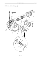
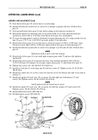
85. Turn helical drive gear (8) several times to seat bearings.
86. Install dial indicator (position A) on carrier (6) so plunger is against side face of helical drive
gear (8).
87. Push and pull helical drive gear (8) and check reading on dial indicator (position A).
88. Alternately tighten two adjusting nuts (4) one notch width (5) at a time until dial indicator
(position A) reads 0.000 in. (0.00 mm) when helical drive gear (8) is push/pulled.
89. To ensure bearing preload, continue alternately turning adjusting nuts (4) to align notches for lock
tabs (3) up to 1.75–7.5 in. (4.45–19.05 cm) notch widths (5) for both sides.
90. Rotate helical drive gear (8) in one direction to check for runout of 0.008 in. (0.203 mm) or less.
If runout is more than 0.008 in. (0.203 mm) replace helical drive gear (8) and pinion gear (7).
91. Install dial indicator (position B) on carrier (6) so plunger is on flat side of tooth of helical drive
gear (8).
NOTE
Hold pinion shaft or gear to prevent turning.
92. Rotate helical drive gear (8) to set teeth tight on pinion gear teeth (7) and zero dial indicator
(position B).
93. Rotate helical drive gear (8) in opposite direction. Gear backlash should be 0.007–0.014 in.
(0.178–0.356 mm). If reading is out of range, replace pinion gear (7) and helical drive gear (8).
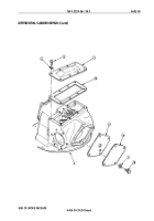
94. Tighten four screws (10) 116–149 lb-ft (157–202 N
•
m).
95. Install two lock tabs (3) on bearing caps (9) with two screws (2). Tighten screws (2) 16–20 lb-ft
(22–27 N
•
m).
96. Install new safety wire (1) on four screws (10) and two screws (2). Ensure lock tabs (3) are bent in
notches (5).
97. Install new gasket (14) and cover (13) on carrier (6) with eight new lockwashers (11) and
screws (12). Tighten screws (12) 20–35 lb-ft (27–47 N
•
m).
NOTE
Install gasket with tab toward top of carrier.
98. Install new gasket (15) and cover (16) on carrier (6) with four washers (17) and screws (18).
Tighten screws (18) 20–35 lb-ft (27–47 N
•
m).
99. Install differential carrier (WP 0454 00).
100. Fill differential carrier (WP 0020 00).
POSITION B
POSITION A
DIAL INDICATOR
1
2
3
4
5
6
7
8
9
10
~
4
5
Back to Top


