TM-9-2320-361-34 - Page 365 of 764
TM
9-2320-361-34
15-12.
DELlVERY PUMP REPAIR
(Contd)
d.
Assembly
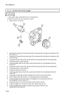
1. Aline locator marks and install liner (3) in pump body (2).
2. Install two rods (5) and four vanes (4) in rotor (1).
3.
4.
5.,
6.
7.
8.
9.
10.
11.
12.
13.
14.
15.
16.
17.
18.
15-54
Position rotor (1) in liner (3).
Install new O-ring seal (19) and pump head (22) on pump body (2) with eight new lockwashers (20)
and screws (21).
Install new O-ring seal (46) and pump head (47) on pump body (2) with eight new lockwashers (49)
and screws (48).
Install new seal (23), washer (24), and new seal (25) in pump head (22) with new snapring (26).
Install bearing (27) in pump head (22).
Install new gasket (28) and cover (30) on pump head (22) with four new Iockwashers (33) and
screws (32).
Install new seal (45), washer (44), and new seal (43) in pump head (47) with new snapring (42).
Install bearing (41) in pump head (47).
Install new seal (35) in cover (36).
Install new gasket (34) and cover (36) on pump head (47) with four new lockwashers (39) and
screws (40).
Install grease fittings (29) and (38) and fittings (31) and (37) in covers (30) and (36).
Position bypass valve (18), spring (17), and spring guide (16) in pump body (2).
Install new gasket (15) and cover (9) over spring guide (16) on pump body (2) with four
new Iockwashers (14) and screws (13).
Install setscrew (10) in cover (9) with locator mark even with cover (9).
Install new gasket (11) on setscrew (10) and cover (9) with valve cap (12).
Install new gasket (50) and strainer body (6) on pump body (2) with four new
lockwashers (7) and screws (8).
Back to Top

