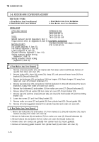
TM-9-2320-361-34 - Page 65 of 764
TM 9-2320-361-34
3-5. FLYWHEEL AND TRANSMISSION ADAPTER PLATE MAINTENANCE
THIS TASK COVERS:
a. Adapter Plate Removal
d. Flywheel Installation
b. Flywheel Removal
e. Adapter Plate Installation
c. Cleaning, Inspection, and Repair
INITIAL SETUP
APPLICABLE MODELS
All
TOOLS
General mechanic’s tool kit
(Appendix B, Item 1)
Torque wrench, l/2-in. dr. (Appendix B, Item 7)
FABRICATED
TOOLS
Flywheel guide screw (Appendix D, Item 3)
MATERIALS/PARTS
Six lockscrews (Appendix F, Item 114)
Thirteen lockwashers (Appendix F, Item 123)
Gasket (Appendix F, Item 38)
REFERENCES (TM)
TM 9-2320-361-10
TM 9-2320-361-20
TM 9-2320-361-34P
TM 9-2815-210-34-2-2
EQUIPMENT CONDITION
.
Wheels
chocked (TM 9-2320-361-10).
●
Battery ground cable disconnected
(TM 9-2320-361-20).
. Pressure plate and clutch disc removed (para. 4-1).
GENERAL SAFETY INSTRUCTIONS
Flywheel is heavy. Use care when removing flywheel.
a.
Adapter Plate Removal
1. Remove thirteen nuts (6) and lockwashers (5) from adapter plate (7) and flywheel housing studs (2)
Discard lockwashers (5).
2. Remove adapter plate (7) and gasket (4) from flywheel housing (l). Discard gasket (4).
b.
Flywheel Removal
WARNING
Flywheel is heavy. Use care when removing flywheel. Failure to do
so may result in injury to personnel.
1. Remove one of six lockscrews (8) from approximately six o’clock position on flywheel (10). Discard
lockscrew (8).
2.
Install guide screw through flywheel (10) in crankshaft (3).
3. Remove five remaining lockscrews (8) from flywheel (10). Discard lockscrews (8).
4. Remove flywheel (10) from crankshaft (3) and guide screw.
5. Remove guide screw from crankshaft (3).
I
c. Cleaning, Inspection, and Repair
1. For general cleaning instruction, refer to para. 2-8.
2. For general inspection instructions, refer to para. 2-9.
3. For repair of flywheel and components, refer to TM 9-2815-210-34-2-2.
d.
Flywheel Installation
1.
Locate the X (11) marked on crankshaft (3) above one of six screw holes and install guide
screw in marked hole.
3-14
Back to Top


