TM-9-2320-362-14-P - Page 45 of 353
TM 9-2320-362-14&P
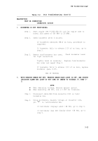
Table 3-2.
Unit Troubleshooting (Cont’d)
MALFUNCTION
TEST OR INSPECTION
CORRECTIVE ACTION
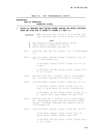
5.
ENGINE OIL PRESSURE GAGE DISPLAYS NORMAL READING AND STATUS INDICATOR
ALARM AND LIGHT ARE ON (REFER TO FIGURES 3-1 THRU 3-3)
Condition:
HMMWV engine has been running 10 to 15 minutes. Both
light and alarm tests on status indicator are normal.
NOTE
●
When measuring voltage, measure against ground.
●
Normal engine oil pressure is 25-50 psi.
●
Before starting procedure, see para 1-1.
Step 1.
Disconnect cable W64 from connector 12J1 on tach/hourmeter
box.
Step 2.
Using multimeter,
measure voltage at connector 12J1, pin
"C",
on tach/hourmeter box.
If multimeter displays correct voltage (fig 3-3), go
to step 3.
If multimeter does NOT display correct voltage (fig 3-
3), go to step 5.
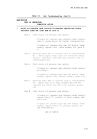
Step 3.
Reconnect cable W64 to connector 12J1 on tach/hourmeter
box.
Disconnect cable W64 from connector on shelter.
Step 4.
Using multimeter,
measure voltage at cable W64, pin “C.”
If multimeter displays correct voltage (fig 3-3),
refer to system manual for further troubleshooting.
If multimeter does NOT display correct voltage (fig 3-
3), replace faulty cable assembly W64 (para 3-25).
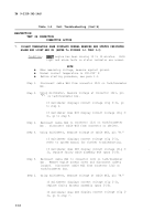
Step 5.
Reconnect cable W64 to connector 12J1 on tach/hourmeter
box .
Remove engine access cover and disconnect safety
lanyard.
Disconnect cable W66 from connector 12J2 on
tach/hourmeter box.
Step 6.
Using multimeter,
measure voltage at cable W66, pin “C.”
If multimeter displays correct voltage (fig 3-3),
replace faulty harness assembly (para 3-20).
If multimeter does NOT display correct voltage (fig 3-
3), go to step 7.
3-15
Back to Top

