TM-9-2320-362-14-P - Page 80 of 353
TM 9-2320-362-14&P
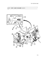
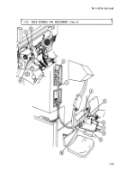
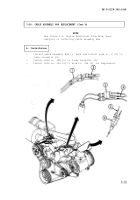
3-26. CABLE ASSEMBLY W66 REPLACEMENT
This task covers:
a. Removal
b. Installation
INITIAL SETUP:
Tools
General mechanic’s tool kit:
automotive (Item 1, Section III,
Appendix B)
Soldering gun (Item 2,
Section III, Appendix B)
Manual References
TM 9-2320-280-10
TM 9-2320-280-20
Materials/Parts
Antiseize compound, conductive
(Appendix C, Item 1)
One connector
P/N MS27144-2
a. Removal
1.
2.
3.
4.
5.
6.
7.
8.
9.
3-50
Materials/Parts (Cont’d)
Solder, tin alloy (Appendix C,
Item 8)
Tie-traps (as required)
P/N MS3367-2-0
Equipment Condition
●
Hood raised and secured
(TM 9-2320-280-10)
●
Battery ground cable disconnected
(TM 9-2320-280-20)
General Safety Instructions
Wear protective eye wear while
performing any soldering.
NOTE
Use figure 3-2, Engine
removing or installing
Electrical Interface, when
cable assembly W66.
Remove four screws (13) and pull out instrument cluster (14).
Unlatch two flexible latches (9) from keepers (7) on engine
access cover holddown brackets (6).
Unlatch two engine access cover holddown latches (8) from engine
access cover holddown strikes (l).
Turn two ring studs (5) and pull engine access cover (4) out
until end of safety lanyard (10) is reached.
Disconnect cable assembly W66 (11) from connector on tach/hourmeter
box (3).
Unhook safety lanyard (10) from safety tab (2). Remove engine access
cover (4).
Remove wire no.
28 (16) from 3-way connector (12).
Cut connector (17) from wire no. 28 (16).
From engine side, pull out wire no.
28 (16) from cowl grommet (15).
Back to Top


