TM-9-2320-365-20-2 - Page 429 of 1432
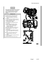
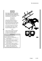
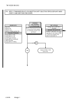
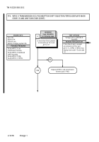
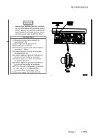
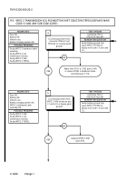
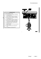
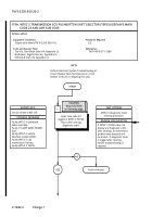
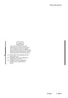
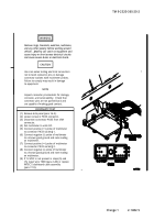
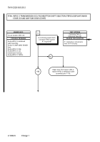
CONTINUITY TEST
CONTINUITY TEST
(1)
Loosen screw in connector J116.
(2)
Disconnect connector J116 from WTEC II
VIM.
(3)
Set multimeter to ohms.
(4)
Connect positive (+) probe of multimeter
to WTEC II VIM connector pin L1.
(5)
Connect negative (-) probe of multimeter to
ground and note reading on multimeter.
(6)
Connect positive (+) probe of multimeter
to WTEC II VIM connector pin L2.
(7)
Connect negative (-) probe of multimeter to
ground and note reading on multimeter.
(8)
If continuity is not present in steps (5) and
(7), replace WTEC
II VIM (para 8-6).
(9)
Connect connector J116 to WTEC II VIM.
(10)
Tighten screw in connector J116.
(11)
Install kick panel (para 16-3).
TM 9-2320-365-20-2
Change 1
2-1481
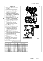
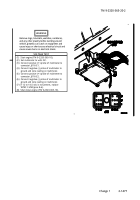
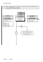
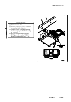
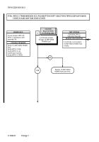
(1)
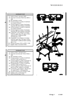
Loosen screw in connector PX33.
(2)
Disconnect connector PX33 from WTEC II
VIM.
(3)
Set multimeter to ohms.
(4)
Connect positive (+) probe of multimeter
to connector PX33-K1.
(5)
Connect negative (-) probe of multimeter
to ground and note reading on multimeter.
(6)
Connect positive (+) probe of multimeter
to connector PX33-K2.
(7)
Connect negative (-) probe of multimeter
to ground and note reading on multimeter.
(8)
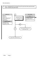
If continuity is not present on connector
PX33-K1, repair wire 3101 (para 2-40) or
replace WTEC II dashboard cable
assembly (para 7-10).
(9)
If continuity is not present on connector
PX33-K2, repair wire 3102 (para 2-40) or
replace WTEC II dashboard cable assembly
(para 7-10).
(10)
Connect connector PX33 to WTEC II VIM.
(11)
Tighten screw in connector PX33.
Back to Top

