TM-9-2320-366-20-1 - Page 555 of 1824
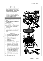
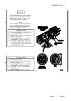
(11)
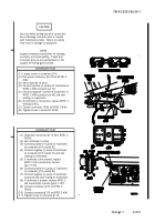
Connect connector P111 to connector
J111.
(12)
Install PDP on dashboard with three
washers and screws.
(13)
Install three screws in PDP.
(14)
Install PDP cover (TM 9-2320-366-10-2).
TM 9-2320-366-20-1
Change 1
2-355
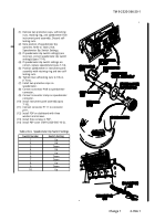
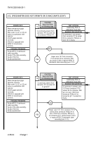
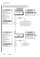
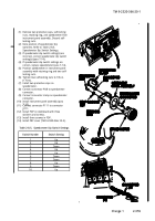
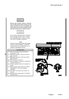
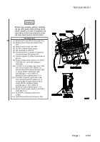
(1)
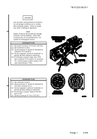
Remove two protective caps, self-locking
nuts, retaining ring, and speedometer from
instrument panel assembly. Discard self-
locking nuts.
(2)
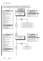
Note position of speedometer dip
switches. Refer to Table 2-8.5.
Speedometer Dip Switch Settings.
(3)
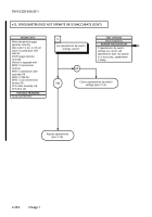
If speedometer dip switch setting(s) are
incorrect, correct speedometer dip switch
setting(s) (para 7-14).
(4)
If speedometer dip switch settings are
correct, replace speedometer (para 7-14).
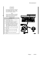
(5)
Position speedometer in instrument panel
assembly with retaining ring and two self-
locking nuts.
(6)
Tighten two self-locking nuts to 9 lb-in.
(1 N·m).
(7)
Install two protective caps on
speedometer.
(8)
Connect connector PX8 to speedometer
connector.
(9)
Connect connector clamp on speedometer
connector.
(10)
Install instrument panel assembly (para
7-10).
1
2
3
4
5
6
7
8
9
10
Up
Up
Down
Up
Up
Down
Down
Up
Down
Up
Switch Number
Switch Setting
Table 2-8.5.
Speedometer Dip Switch Settings
Back to Top

