TM-9-2320-366-20-3 - Page 954 of 1396
TM 9-2320-366-20-3
7-34. M1089 WRECKER CONTROL PANEL TOGGLE SWITCH REPLACEMENT
This task covers:
a. Removal
b. Installation
c. Follow-On Maintenance
INITIAL SETUP
Equipment Conditions
Engine shut down (TM 9-2320-366-10-1).
Batteries disconnected (para 7-57).
Tools and Special Tools
Tool Kit, Genl Mech (Item 46, Appendix C)
Tool Kit, Electrical (Item 45, Appendix C)
Heater, Gun Type, Electric (Item 24, Appendix B)
Material/Parts
Dispenser, Pressure Sensitive Adhesive Tape
(Item 20, Appendix D)
Insulation Sleeving, Electrical (Item 29, Appendix
D)
Lockwasher (8) (Item 100, Appendix G)
Lockwasher (Item 74, Appendix G)
Nut, Self-Locking (2) (Item 134, Appendix G)
Splice, Conductor (2) (Item 275, Appendix G)
Splice, Conductor (Item 276, Appendix G)
a. Removal.
NOTE
There are seven toggle switches on the
WRECKER CONTROL PANEL.
Steps (1
and 2) apply to all seven toggle switches.
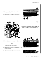
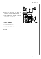
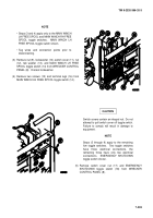
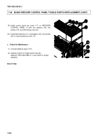
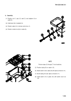
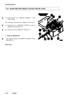
(1) Remove eight screws (1), lockwashers (2), and washers
(3)
from
control
panel
top
cover
(4).
Discard
lockwashers.
(2) Remove two self-locking nuts (5), four washers (6), two
screws (7), and control panel top cover (4) from
WRECKER CONTROL PANEL (8). Discard self-locking
nuts.
7-202
Back to Top

