TM-9-2320-366-20-4 - Page 858 of 1558
TM 9-2320-366-20-4
Section II. MAINTENANCE PROCEDURES
12-2. WHEEL REPAIR
This task covers:
a. Disassembly
b. Assembly
c. Follow-On Maintenance
INITIAL SETUP
Equipment Conditions
Tire removed (TM 9-2320-366-10-2).
CTIS hose assemblies, manifold valve, kneeling valve
and bracket removed (para 12-5).
Tools and Special Tools
Tool Kit, Genl Mech (Item 46, Appendix C)
Iron, Tire (Item 20, Appendix C)
Wrench, Torque, 0-600 lb-ft (Item 60, Appendix C)
Wrench Set, Socket (Item 50, Appendix C)
Materials/Parts
Packing, Preformed (Item 190, Appendix G)
Nut, Self-Locking (20) (Item 145, Appendix G)
Nut, Self-Locking (4) (Item 171, Appendix G)
Personnel Required
(2)
References
TM 9-2610-200-14
WARNING
•
Ensure that tire is totally deflated before removing self-locking nuts. Failure to comply may result
in serious injury or death to personnel.
•
Always use an inflation safety cage to inflate tires mounted on multipiece rims, and tire/rim
assemblies not mounted on a tire changing machine that has a positive lock down device designed
to hold the assembly during inflation (TM 9-2610-200-14). When using a tire changing machine,
always follow manufacturer’s mounting and safety instructions. Failure to comply may result in
serious injury or death to personnel.
Always inflate tires that are mounted on rims with
demountable side ring flanges or lockrings in an inflation safety cage or serious injury or death
may result.
a. Disassembly.
CAUTION
Loosen self-locking nuts no more than 1/2
inch (1.27 cm) at a time. Failure to comply
may result in damage to equipment.
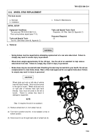
(1) Loosen 20 self-locking nuts (1) approximately 1/2 in.
(1.27 cm) at a time.
(2) Remove 20 self-locking nuts (1) from outside wheel
section (2). Discard self-locking nuts.
(3) Remove outside wheel section (2) from tire (3).
(4) Remove preformed packing (4) from inside wheel section
(5). Discard preformed packing.
12-2
Back to Top


