TM-9-2320-386-24-1-1 - Page 664 of 1078
CLEANING, INSPECTION, AND REPAIR
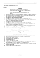
For cleaning, inspection, and repair of tires and rims, refer to TM 9-2610-200-14.
ASSEMBLY
1.
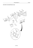
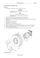
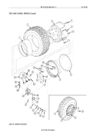
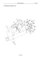
Apply sealant to threads of elbows (12), (20), (21), (28), and (33), adapters (13) and (32),
connector (14), and valve (25).
NOTE
Assistant will help with steps 2 and 3.
2.
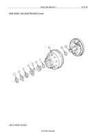
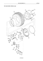
Center beadlock (1) in tire (2).
3.
Install grommet (6) and turret valve (5) on inner rim (3) with nut (7). Tighten nut (7) 40-65 lb-ft
(54-88 N
•
m).
NOTE
Assistant will help with step 4.
Do not stretch or twist seal.
Lubricate O-ring before installation.
4.
Install beadlock (1) and tire (2) on inner rim (3).
5.
Install new O-ring (8) on groove of inner rim (3).
6.
Install outer rim (9) on ten inner rim studs (4) with new locknuts (34). Finger-tighten locknuts (34).
7.
Alternately and evenly tighten ten locknuts (34) on inner rim studs (4). Tighten locknuts (34)
425-475 lb-ft (576-644 N
•
m).
8.
Install air valve (24) on mounting bracket (10) with four screws (11) and new locknuts (23).
9.
Install mounting bracket (10) on two studs (4) with nuts (22).
CAUTION
Elbows must be installed in their proper position and location as
previously noted. Failure to do so may cause kinking to air lines
when installed.
10.
Install elbow (21) on air valve (24).
11.
Install valve (25), valve core (26), and cap (27) on elbow (21).
12.
Install elbows (20) and (28) on air valve (24).
13.
Install elbow (12) on turret valve (5).
14.
Install adapters (13) and (32) on elbows (12) and (33).
15.
Install connector (14) on adapter (13).
16.
Install air tube (17) on connector (14) with sleeve (15) and nut (16).
17.
Install air tube (17) on elbow (20) with sleeve (19) and nut (18).
18.
Install counterweight (36) on inner rim stud (4) with nut (35).
19.
Install air tube (31) on adapter (32) and elbow (33).
20.
Install air tube (31) on elbow (28) with sleeve (30) and nut (29).
21.
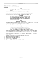
Inflate tire to proper pressure (TM 9-2320-386-10).
22.
Install tire and wheel (WP 0174 00).
23.
Start engine (TM 9-2320-386-10) and allow air pressure to build. Check for air leaks.
TM 9-2320-386-24-1-1
0175 00
TIRE AND WHEEL REPAIR (Contd)
0175 00-4
Back to Top

