TM-9-2320-386-24-1-1 - Page 901 of 1078
0243 00-2
TM 9-2320-386-24-1-1
0243 00
PERSONNEL HOT WATER HEATER SWITCH REPLACEMENT (Contd)
REMOVAL
NOTE
Locking hardware in step 1 is provisioned with switch.
1.
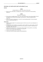
Remove nut (9), lockwasher (8), locking ring (7), plate (6), and switch (11) from mounting
bracket (5).
NOTE
Tag leads for installation.
2.
Remove three assembled-washer screws (14), resistor lead wire-low (12), lead wire 400A (13), lead
wire 400 (15), and resistor lead wire-high (4) from switch (11). Discard assembled-washer
screws (14).
3.
Remove two nuts (2), lockwashers (1), screws (10), and mounting bracket (5) from instrument
panel (3). Discard lockwashers (1).
INSTALLATION
1.
Install mounting bracket (5) on instrument panel (3) with two screws (10), new lockwashers (1),
and nuts (2).
2.
Install resistor lead wire-high (4) on top position, lead wire 400 (15) on center position, and lead
wire 400A (13) and resistor lead wire-low (12) on lower position of switch (11) with three new
assembled-washer screws (14).
3.
Install plate (6) and switch (11), with resistor lead wire-high (4) at top position, on mounting
bracket (5) with locking ring (7), lockwasher (8), and nut (9).
4.
Connect battery ground cable (WP 0121 00).
5.
Check heater switch for proper operation (TM 9-2320-386-10).
Back to Top

