TM-9-2320-387-24-1 - Page 321 of 1205
TM 9-2320-387-24-l
REFERENCE INFORMATION
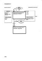
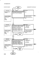
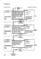
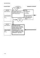
STARTER CIRCUIT
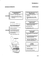
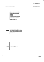
Don’t forget that your vehicle batteries
are disconnected.
so you can’t run the
STEACE-R from the DCA. You have to
use the power cable and connect
directly to the batteries.
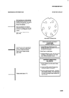
When the resistance is too high for
STUICE-R
to measure, as in the case
of an open circuit, STEXE-R
displays
.9.9.9.9.
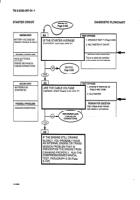
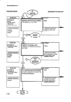
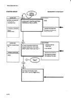
Repair wiring or replace harness
(para. 4-80).
Check the wires at the connectors
for
shorts.
If there are no visible shorts,
you have to replace the harness.
I
Repair wiring or replace harness
(para. 4-80).
-1
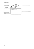
Replace starter (para. 4-11).
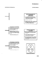
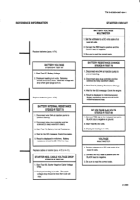
PCB BODY CONNECTOR
RESISTANCE
AND CONTINUITY
04,500
OHMS
STE/lCE-R TEST 91
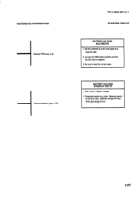
1. Connect RED clip and BLACK clip to the
indicated test points in the question. RED to the
first, BLACK to the second.
I
2. Start Test 91,0-4.800
Ohms.
3. Displayed reading is in ohms. Less than 5 ohms
is continuity.
If the resistance is over 45OCl
ohms, STEIICE-R
displays .9.9.9.9.
CONTINUITY
(RESISTANCE)
MULTIMETER
I
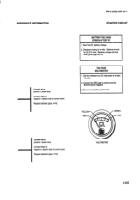
1. Set me voltmeter to an ohms scale of about
1 .OOO ohms.
2. Connect the RED and BLACK leads to the
connections
stated in the question.
3. Be sure to read the correct scale.
Less than 5
ohms indicates continuity.
For an open circuit,
the meter should peg full scale (needle all the
way to the left).
2-265
Back to Top

