TM-9-2320-387-24-2 - Page 1113 of 1555
TM
9-2320-387-24-2
28-17.
CONTROL
VALVE AND ACCUMULATOR
HOUSING REPAIR
(Cont’d)
c.
Control Valve
Disassembly
1.
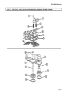
Remove manual valve (30) from body
(2).
2.
Remove screen filter (1) from body (2).
NOTE
A 5/64_in. (l-984-mm) drill bit may be used to remove spring pins.
While rotating drill bit, lift and remove spring pins.
3.
4.
Remove spring pin (9), plug (81, ball (71, bushing (61, O-ring (5),3-4 shift valve (4), and spring (3)
from body (2). Discard O-ring (5).
Remove capscrew (lo), 2-3 shift solenoid (111, spring pin (12),2-3 shift valve (131, and spring (14)
from body (2).
5.
Remove capscrew (18), l-2 shift solenoid (191, spring pin (171, 1-2 shift valve (161, and spring (15)
from body (2).
6.
Remove spring pin (201, plug (211, and filter (22) from body (2).
7.
Remove sleeve (251, plug (24), and ball (23) from body (2).
8.
Remove capscrew (311, clamp (32), and pressure control solenoid (33) from body (2).
9.
Remove
clip (371, PWM solenoid (381, spring pin (361, TCC valve (351, and spring (34) from
body (2).
10.
Remove retainer plate (39), spring (40), and feed-limit valve (41) from body (2).
11.
Remove spring pin (261, plug (271, spring (281, and accumulator valve (29) from body (2).
d.
Control
Valve Cleaning
Clean all parts in accordance with para. 2-14.
e. Control
Valve
Inspection
1.
Inspect valves (41, (131, (16), (291, (30), (35), and (41) and bushing (6) for scoring, nicks, and
scratches. Replace control valve assembly if damaged.
2.
Inspect shift solenoids (11) and (19) for O-ring damage. Replace if damaged.
3.
Inspect springs (31, (141, (151, (28), (341, and (40) for damage or distorted coils. Replace springs that
are damaged.
4.
Inspect body (2) for cracks, interconnected passages, and damaged machined surfaces. Replace
control valve if damaged.
5.
Inspect screen filter (1) for damage. Replace if damaged.
f. Control Valve Assembly
1.
2.
3.
4.
5.
6.
7.
28-62
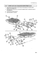
Install accumulator valve (29), spring (281, and plug (27) in body (2) with spring pin (26).
Install feed-limit valve (41) and spring (40) in body (2) with retainer plate (39).
Install spring (34) and TCC valve (35) in body (2) with spring pin (36). Install PWM solenoid (38)
with clip (37).
Install clamp (32) and pressure control solenoid (33) in body (2) with capscrew (31).
Install ball (23) and plug (24) in body (2) with sleeve (25).
Install filter (22) and plug (21) in body (2) with spring pin (20).
Install spring (15) and l-2 shift valve (16) in body (2) with spring pin (17). Install l,-2 shift
solenoid (19) with capscrew (18).
Back to Top

