TM-9-2320-387-24-2 - Page 484 of 1555
TM 9-2320-387-24-2
12-68.22
Change 1
12-36.5. 10,500 LB REAR HYDRAULIC WINCH VALVE ASSEMBLY REPLACEMENT (Cont’d)
NOTE
Ensure area around valve assembly ports are clean before
removing hoses.
6.
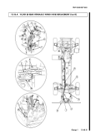
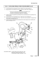
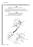
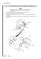
Disconnect hydraulic hose assembly (2) from port 1 elbow (3) on valve assembly (1).
7.
Disconnect hydraulic hose assembly (5) from port 3 elbow (4) on valve assembly (1).
8.
Disconnect hydraulic hose assemblies (9) and (8) from port 2 adapter (6) and port 4 adapter (7)
on valve assembly (1).
NOTE
Perform step 9 only if vehicle is to be operated with valve
assembly removed. Tube assembly is located in stowage box
under commander's (companion) seat inside vehicle.
9.
Connect tube assembly (10) to hydraulic hose assemblies (2) and (5).
10
2
5
1
2
3
4
5
1
6
7
8
9
PORT 1
PORT 3
PORT 2
PORT 4
Back to Top

