TM-9-2330-202-13-P - Page 50 of 552
Hydraulic Brake System (M101A2, M101A3, M116A2, and M116A3) - Continued
e.
Breakaway Lever. The breakaway lever is activated by the breakaway chain and controls the master
cylinder. When the breakaway lever is up, the brakes are applied. When the breakaway lever is
down, the drawbar coupler movement controls the master cylinder.
f.
Leaf Spring. The leaf spring holds the breakaway lever up. The breakaway lever must be reset any
time it has been pulled up.
g.
Hydraulic Brake Tube Assemblies and Hose Assembly. These components transfer hydraulic
pressure from the master cylinder to the wheel cylinders.
h.
Wheel Cylinders. One wheel cylinder is located at each wheel. The wheel cylinder changes hydraulic
pressure into mechanical motion. When the wheel cylinder is pressurized, it pushes the primary and
secondary brakes hoes against the brake drum.
i.
Primary Brake Shoe. The primary brake shoe is pushed against the brake drum by the wheel
cylinder. The brake drum pushes the primary brake shoe down and into the secondary brake shoe.
j.
Secondary Brake Shoe. The secondary brake shoe provides braking action. It is pushed into the
brake drum by the primary brake shoe.
BREAKAWAY
LEVER
LEAF
SPRING
BRAKES APPLIED
BRAKES APPLIED
FRONT AND
REAR TUBE
ASSEMBLIES
HOSE ASSEMBLY
LEFT AND
RIGHT TUBE
ASSEMBLIES
WHEEL
CYLINDER
SECONDARY
BRAKE SHOE
SECONDARY
BRAKE SHOE
WHEEL
CYLINDER
PRIMARY
BRAKE SHOE
PRIMARY
BRAKE SHOE
BRAKES RELEASED
M116_M101_015
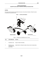
Figure 2.
Components of Hydraulic Brake System.
TM 9-2330-202-13&P
0003
0003-2
Back to Top


