TM-9-2330-227-14-P - Page 229 of 576
TM 9-2330-227-14&P
TIRE AND WHEEL ASSEMBLY - CONTINUED
ACTION
LOCATION
ITEM
REMARKS
INSTALLATION - CONTINUED
NOT E
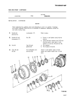
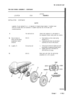
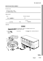
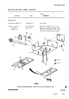
Lugbolts (7) are marked R. or L. in direction of forward wheel rotation. To tighten stud
nuts (6) on right side, turn clockwise. To tighten stud nuts (6) on left side, turn
9.
10.
11.
12.
counterclockwise.
Side of frame (3)
where tire and wheel
assembly is being
removed
Lugbolts (7)
Six stud nuts (6)
Axle (4)
Six stud nuts (6)
Axle (4)
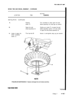
Screw onto Iugbolts (7), and tighten in
the sequence shown using stud nut wrench.
a.
b.
a.
b.
Take trestles out from under spring
brackets (5.1).
Lower jack until inner tire and wheel
assembly (5) rests on the ground.
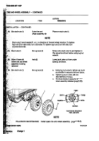
Using stud nut wrench, tighten as much
as possible in sequence shown below.
Tighten stud nuts to 400-425 ft-lb
(540-560 Nm) of torque.
Raise jack until inner tire and wheel
assembly (5) is off of ground.
Change 1
4-148.3
Back to Top

