TM-9-2330-328-14-P - Page 122 of 254
TM9-2330-328-14&P
MAINTENANCE OF AIR BRAKE SYSTEM - Continued
0016 00
SERVICE BRAKES - Continued
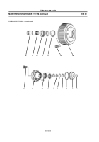
(e) Install bearing assembly
(9)
on axle bracket
(19)
with three screws
(8)
,
lock washers
(7)
and hex nuts
(6)
.
(f)
Coat length of camshaft
(3)
with grease, lithium base NGLI Grade 1, and
insert through bushing
(17)
. Place washer
(5)
on camshaft and insert
camshaft through bearing assembly
(9)
.
(g) Install lock ring
(4)
using lock ring pliers.
(h) Install slack adjuster and lock ring (WP 0016 00-11).
(i)
Install brake shoes (WP 0016 00-7).
NOTE
It may be necessary to remove slack adjuster to align camshaft with shoe anchor pins.
(j)
Install hubs and drums (WP 0016 00-1).
(k) Install wheels (WP 0012 00-3).
c. Brake Adjustment (Slack Adjustment).
NOTE
Brake adjustment must be done with brake air chambers uncaged and air in the system.
(1) Jack up wheel to be adjusted.
(2) Apply a 9/16 inch wrench to hex head
(1)
of worm shaft and push in against the slack
adjuster
(2)
to unlock the worm shaft.
(3) Turn the hex head
(1)
of the worm shaft clockwise on slack adjuster until the wheel
cannot be turned.
(4) Back off the worm shaft hex head
(1)
until the wheel turns freely. Check clearance
between brake shoes and drum with feeler gage. Clearance should be 0.005 inch. Adjust
worm shaft hex head
(1)
to meet specified clearance.
(5) Lower jack and remove from axle.
(6) Repeat steps
(1)
through
(5)
for other slack adjusters as required.
0016 00-10
Back to Top


