TM-9-2330-342-10 - Page 441 of 500
CHECK/ADJUST TIRE AIR PRESSURE - Continued
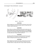
WARNING
Never inflate a tire without checking to ensure that the side ring is still
properly seated and the lockring is properly seated in the lockring groove.
Ensure that the side ring, lockring and lockring groove are not damaged.
The side ring and lockring may blow off during inflation/deflation. Failure
to comply may result in injury or death to personnel.
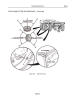
WARNING
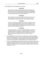
When inflating tires mounted on the trailer, all personnel must remain out
of the trajectory of the side ring and lockring as shown by the areas
indicated. Failure to comply may result in injury or death to personnel.
WARNING
If the tire has been driven on when under inflated or overinflated or there
is obvious or suspected damage on the tire or wheel components, the tire
must be completely deflated. To deflate the tire, remove the valve core
from the valve stem and stand out of the trajectory area. Failure to comply
may result in injury or death to personnel.
WARNING
If tire has been run flat, or is over or under inflated when tire is measured
and operating terrain is compared to Unsafe Tire Inflation Pressures, or
if wheel/tire assembly has obvious or suspected damage, it is not safe to
adjust tire pressure. Completely deflate tire and remove tire from axle.
Failure to follow these procedures may result in injury or death to
personnel.
8.
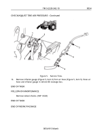
If tire is underinflated or overinflated or if the wheel or tire has obvious damage or
suspected damage, stand out of trajectory range. Remove inflation gauge (Figure 5,
Item 3) from air hose (Figure 5, Item 5) and press handle (Figure 5, Item 4) until all
air pressure has exhausted from inflation gauge. When tire is completely deflated,
remove from trailer and take to Field Maintenance for disassembly and repair.
9.
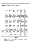
If tire is not underinflated or overinflated and the wheel or tire does not have obvious
damage or suspected damage, stand out of trajectory range and inflate or deflate until
proper pressure (refer to Table 1.) is attained. Press in latch handle (Figure 4, Item
2) and pull air chuck (Figure 4, Item 3) from valve stem (Figure 4, Item 1). Install valve
cap (Figure 4, Item 4).
TM 9-2330-342-10
0054
0054-7
Back to Top

