TM-9-2330-342-23-P - Page 80 of 1348
LOCATION AND DESCRIPTION OF MAJOR COMPONENTS - Continued
1
2
3
4
5
6
7
8
9
10
11
12
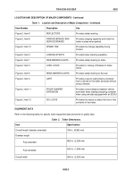
Figure 2.
Location and Description of Major Components.
Table
1.
Location and Description of Major Components.
Item Number
Description
Use
Figure 1, Item 6
DRAWBAR
Provides a simple way to pull and guide the
trailer.
Figure 1, Item 5
12V/24V VEHICULAR
LIGHTING CONNECTORS
12 and 24 volt adapter connectors provide
connectors for the vehicle 12 volt/24 volt
system to be hooked to the trailer.
Figure 1, Item 7
SAFETY CHAINS
Provides a safety backup to drawbar.
Figure 1, Item 8
AIR LINES
Provides a means to link air system of vehicle
to trailer.
Figure 1, Item 9
TURNTABLE
Provides front axle steering.
Figure 1, Item 10
STOWAGE BOX
Provides a place to store Basic Issue Items.
Figure 1, Item 11
TIRES
Provides excellent cross-country mobility.
Figure 1, Item 1
FRAME
Provides a main support for loads and flatrack.
Figure 1, Item 3
Figure 2, Item 6
LIFTING EYES
Provides means to lift trailer.
Figure 1, Item 2
GUIDE RAILS
Provides guides for flatrack or cart during
loading and unloading.
Figure 1, Item 4
DATA PLATES
Provides information on operation and
technical details of the trailer.
Figure 2, Item 7
REAR COMBINATION
LIGHTS
Provides stop, turn, and blackout lights.
TM 9-2330-342-23&P
0002
0002-2
Back to Top


