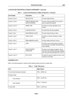
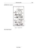
TM-9-2330-342-23-P - Page 88 of 1348
PALLETIZED LOAD SYSTEM TRAILER (PLST) M1076 A1 - Continued
Item 3) of sufficient length to reach the towing vehicle. Two towing eyes, at the rear of the PLST M1076 A1 (Figure
1, Item 7) permit towing with a medium-duty tow bar. The spare-tire carrier is behind the first axle (Figure 1, Item 5).
The spare-tire is held in place with bolts through the wheel bolt pattern. The spare tire and wheel assembly can be
raised and secured in the spare tire carrier by the trailer-provided hand-operated winch. The PLST M1076 A1 (Figure
1, Item 7) uses turntable-type steering for tracking and turning and is equipped with a two position adjustable drawbar
(Figure 1, Item 4). The PLST M1076 A1 (Figure 1, Item 7) is also equipped with an air braking system. All three axles
use 16.5 in. diameter by 7 in. wide (419 mm by 178 mm) S-cam brakes. The PLST M1076 A1 (Figure 1, Item 7) has
a dual brake system with separate service and emergency brake system. The PLST M1076 A1 (Figure 1, Item 7)
brake system is activated and charged by the vehicle air supply. The brakes are self-adjusting.
PLST SERVICE BRAKES
The six service brakes on the PLST M1076 A1 are powered by 24/20 in. (610/508 mm) brake chambers. Six-inch
automatic slack adjusters are provided with all brake chambers. The service brakes are activated when a signal from
the foot-operated treadle valve or hand-operated control valve is sent through a series of relay valves. The relay
valves convert the proportioned service-brake signal from the vehicle into a regulated service brake chamber
pressure.
PLST PARKING BRAKES
Spring-chamber parking brakes are provided on all PLST M1076 A1 axles. The application and release of the six
PLST M1076 A1 spring brakes is controlled by a spring brake control valve. An absence of air pressure in the
emergency/spring-brake supply line causes the spring-brake control valve to activate the spring brake. The spring
brake control valve also retains air pressure in the PLST M1076 A1 air reservoir so the PLST M1076 A1 spring
brakes can be released by the spring release valve. The spring-brake control valve also prevents compounding of
pressures in the brake chamber by relieving the pressure on the spring brake side of the chambers when the spring
brakes are set and the service brakes are applied. The PLST M1076 A1 spring brake release valve is located on
the right front corner of the trailer. This valve releases the PLST M1076 A1 spring brakes without a prime mover air
supply when there is sufficient air reservoir pressure. After the spring brakes have been released, they can be
reapplied by actuating the release valve. When air is supplied through the emergency/spring-brake supply line, the
spring release valve is overridden and the trailer spring-brakes are released. If there is insufficient air reservoir
pressure to release the trailer parking brakes, a cage nut release is provided on each spring chamber to mechanically
release the spring brakes.
PLST EMERGENCY BRAKES
Whenever there is a loss of pressure from the vehicle or PLST M1076 A1 air reservoir, the emergency brakes are
activated.
TM 9-2330-342-23&P
0003
0003-2
Back to Top


