TM-9-2350-238-20-1 - Page 1274 of 1364
TM 9-2350-238-20-1
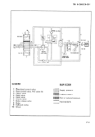
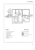
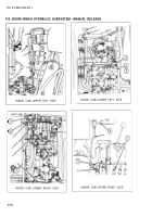
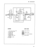
F-5. BOOM WINCH HYDRAULIC SUBSYSTEM.
Functional Description.
a.
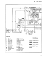
The hydraulic fluid power for the
d.
Moving the handle of the directional
operation of the boom winch is supplied by
control valve ( 1 ) in the PAY OUT position
the hydraulic power subsystem.
has the same effect as in PAY IN except
that the hydraulic fluid is routed in the op-
b.
The boom winch hydraulic subsystem
posite direction through the hydraulic motor
(9). The relief valve (5) controls the rate of
controls the power for boom winch opera-
flow in the return line and prevents free fall
tion when lifting or lowering a load.
of the load.
c .
Move the handle of the directional
e.
When the handle of the directional
control valve (1 ) in the PAY IN position to
control valve ( 1 ) is in the neutral position,
direct hydraulic fluid to release brake (7)
hydraulic fluid flows through the open
and operate the hydraulic motor (9) to
center port to the tow winch directional
retrieve the boom winch wire rope. Return
control valve.
fluid from the hydraulic motor (9) flows
through the pressure relief valve (5) and
f. When the engine is not operating or
the directional control valve ( 1 ), then to the
during hydraulic power failure, the boom
reservoir. The relief valve (4) limits
winch brake can be manually released by
hydraulic pressure when paying in to 1425
setting the brake release valve (7) to HAND
psi (9825 kPa) to protect the winch com -
PUMP PRESSURE and operating the hand
ponents from overload.
pump to lower a load.
F-10
Back to Top

