TM-9-2350-238-20-1 - Page 1282 of 1364
TM 9-2350-238-20-1
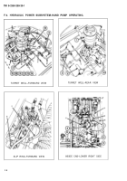
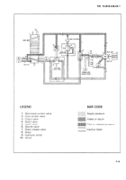
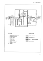
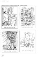
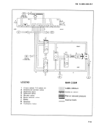
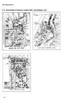
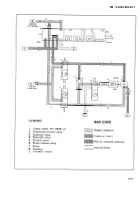
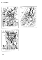
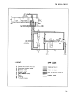
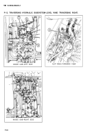
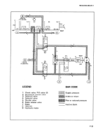
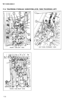
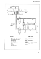
F-9. TRAVERSING HYDRAULIC SUBSYSTEM.
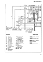
Functional Description.
a.
The hydraulic fluid power for the
direction through the hydraulic motor (9),
operation of the traversing subsystem is
which traverses the cab to the right.
supplied by the hydraulic power subsystem.
e .
When directional control valve (2) is
b.
The traversing hydraulic subsystem
in neutral position, hydraulic fluid flows
controls the power for rotational movement
through the open center port to the flow
of the cab.
divider manifold in the hydraulic power
subsystem.
c .
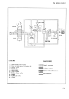
Depressing the forward portion of the
foot pedal of the directional control valve
f.
When the engine is not operating or
(2), directs hydraulic fluid at 2050 psi
during hydraulic power failure, the travers-
(14,135 kpa) through the solenoid valve (4)
ing brake (7) can be manually released by
to the brake release valve (6), releasing the
setting the brake release valve (6) to HAND
brake (7), and to the hydraulic motor (9),
PUMP PRESSURE and operating the hand
which traverses the cab to the left. The
pump, so that the cab can be rotated.
return flow from the hydraulic motor (9)
passes through the solenoid valve (3) and
9 .
During tow winch operation, cab
the directional control valve (2) and back to
traversing is controlled automatically by an
the reservoir.
electrical sensing system. The sensing
system energizes either the solenoid valve
d.
Depressing the rear portion of the
(3) for right traversing, or the solenoid
foot pedal of the directional control valve
valve (4) for left traversing. Hydraulic
(2) has the same effect as when traversing
pressure at 1750 psi (12,066 kPa) is sup-
Ieft, described above, except that the
plied by the 8 gpm pump in the hydraulic
hydraulic fluid is routed in the opposite
power subsystem.
F-18
Back to Top

