TM-9-2350-238-20-1 - Page 16 of 1364
TM 9-2350-238-20-1
1-9. LOCATION AND DESCRIPTION OF MAJOR COMPONENTS (CONT).
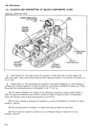
ENGINE MODEL 7083-7395. Engine exhaust gas is routed through two exhaust manifolds and two
exhaust ducts to the turbocharger. The exhaust gas passes through the turbocharger (driving it) and
out through the exhaust elbow.
ENGINE MODEL 7083-7398. Exhaust gases are discharged through two exhaust manifolds and
ducts to the turbocharger. Gases from the right manifold discharge into the turbocharger turbine.
Gases from the left manifold discharge through the turbocharger regulator in the turbocharger.
a.
Turbocharger regulator.
The regulator is controlled by the pressure difference between intake
and outlet air of the turbocharger blower section. When the outlet pressure is greater than the inlet
pressure, the regulator vents part of the exhaust gases through its exhaust pipe to bypass the
turbocharger. This reduces the turbocharger speed and output of air, thus preventing turbocharger
overspeed.
b.
Exhaust elbow.
Exhaust gases are expelled from the turbocharger through an exhaust
elbow.
FIRE EXTINGUISHER SYSTEM
The fixed fire extinguisher system is a carbon dioxide gas system with two release handles. When
either release handle is pulled, two cylinders discharge carbon dioxide gas through nozzles over the
engine and into the powerplant compartment.
FUEL SYSTEM
The engine takes fuel from the cell to the low-pressure fuel filter on the engine. Fuel flows from the
low-pressure fuel filter to the engine fuel pump. The fuel pump delivers fuel through a high-pressure
fuel filter to the injectors at high pressure.
Excess fuel is used to cool the injectors and is returned
to the fuel cell through a return line. Fuel that leaks past moving parts in the engine is collected in
the powerplant reservoir.
a.
Fuel cells.
A steel fuel cell is part of the hull. It is lined with a two-piece fabric fuel cell filled
with foam filler blocks. The fabric fuel cell prevents fuel leakage. The foam filler blocks prevent
sloshing of fuel in the cell.
b.
Air box pump and fuel prime solenoid.
The air box pump and fuel prime solenoid valve,
when energized, allow the pump to draw fuel from the low-pressure filter and force it through the
high-pressure filter to the injectors. This prime and purge system forces out any air trapped in the
high-pressure fuel filter and lines.
HYDRAULIC SYSTEM
The M578 Recovery Vehicle has an open-center type hydraulic system. This means that the
hydraulic fluid continuously circulates through the main hydraulic supply lines. When no hydraulic
subsystem is being used, the hydraulic fluid pressure in the main supply lines is near zero. When a
subsystem is used, hydraulic fluid from the main supply lines is diverted through the subsystem.
Hydraulic fluid pressure builds up within the subsystem to a level high enough for the subsystem to
function. Preset pressure relief or pressure reducing valves protect the subsystem from too much
pressure.
1-8
Back to Top

