TM-9-2350-238-20-1 - Page 230 of 1364
TM 9-2350-238-20-1
2-12. ELECTRICAL CIRCUIT TROUBLESHOOTING (CONT).
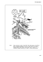
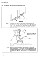
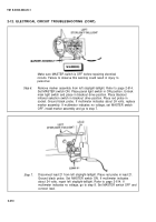
Step 6.
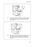
Place red probe in pin socket C. Ground black probe.
indicates 0 ohms, connect electrical lead to low engine coolant level
warning light and go to step 7. If multimeter does not indicate 0 ohms, low
engine coolant level warning switch is operating properly.
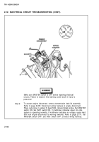
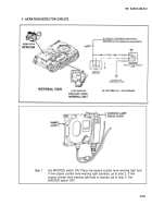
Step 7.
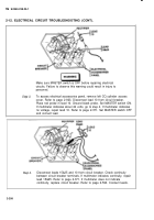
To access aeration detector, remove engine deck assembly. Refer to page
2-935. Disconnect ground lead from aeration detector. Place red probe on
ground lead. Ground black probe. If multimeter indicates 0 ohms, go to
step 9. If multimeter does not indicate 0 ohms, repair ground lead. Refer to
page 2-371. Connect ground lead.
2-204
Back to Top


