TM-9-2350-238-20-1 - Page 368 of 1364
TM 9-2350-238-20-1
2-12. ELECTRICAL CIRCUIT TROUBLESHOOTING (CONT).
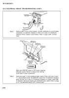
Step 4.
I
Make sure MASTER switch is OFF before repairing
electrical circuits. Failure to observe this warning
could result in injury to personnel.
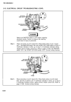
Place red probe on pin E (lead 410). Place black probe on pin C (lead
401 ). Set MASTER switch ON. Set START-OFF-RUN switch to RUN. If
multimeter indicates 0 ohms, go to step 5. If multimeter indicates infinity,
replace driver’s heater control box. Refer to page 2-1029. Set MASTER
switch OFF. Set START-OFF-RUN switch OFF. Connect wiring harness.
Step
5.
Place red probe on pin E (lead 410). Place black probe on pin B (lead
402). Set HI-LO switch to Hl. If multimeter indicates 0 ohms, go to step 6.
If multimeter indicates infinity, replace driver's heater control box. Refer to
page 2-1029. Connect wiring harness.
2-342
Back to Top


