TM-9-2350-238-34-2 - Page 76 of 327
3 4
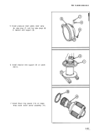
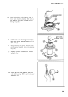
Install shift rod spool assembly (38) and
winch shift rod (40) into cable reel (1)
through motor end until winch shift rod
comes through brake rod of stage one
boom winch carrier assembly (24) at
reaction end of cable reel.
TM 9-2350-238-34-2
ADJUSTMENT
1
2
3
4
5
6
7
Hydraulic system is under high
pressure. Follow hydraulic system
safety procedures to prevent injury
(TM 9-2350-238-20-2). Wipe up
spilled hydraulic fluid.
Refer to TM 9-4940-468-14 for test setup
and testing procedures.
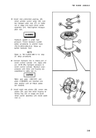
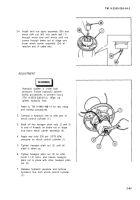
Connect a hydraulic line to inlet port of
winch control cylinder (1).
Back off two hexagon plain nuts (2 and 3)
to end of threads on brake rod of stage
one boom winch carrier assembly (4).
Apply and hold 200 psi (1379 kPa)
pressure on winch control cylinder (1).
Tighten hexagon plain nut (2) until all
slack is taken up.
Tighten hexagon plain nut (2) an addi-
tional 1-1/2 turns, and secure hexagon
plain nut in place with other hexagon plain
nut (3).
Release hydraulic pressure and remove
hydraulic line from winch control cylinder
(1).
2-63
Back to Top


