TM-9-2350-256-20-2 - Page 527 of 1440
TM 9-2350-256-20-2
0277 00
9.
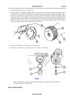
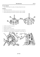
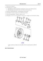
Install outer cone bearing (12).
10.
Install adjusting nut (11) as follows:
a.
Tighten adjusting nut while rotating hub (24) in both directions to ensure contact of all bearing surfaces.
b.
Back off adjusting nut and torque to 50–70 lb-ft (68–95 N•m). Then back off 1/4 turn.
11.
Install ring (10) and align adjusting nut (11) pin and ring hole to lock into place.
12.
Install lockplate (9) and nut (8). Torque nut to 150–300 lb-ft (203–407 N•m).
13.
Install static grounding spring (7), bushing (6), and relief valve (5).
14.
Install gasket (4), access cover (3), six lockwashers (2), and six screws (1). Torque screws to 20–25 lb-ft (27–34 N•m).
NOTE
Follow-on maintenance: Tighten track (refer to TM 9-2350-256-10); Install roadwheel (see WP 0274
00).
END OF WORK PACKAGE
0277 00-5/6 blank
Back to Top

