TM-9-2350-260-20-1-3 - Page 614 of 783
TM 9-2350-260-20-1-3
BRAKE LEVER AND LINKAGE ASSEMBLIES (LEFT AND RIGHT) REPAIR AND REPLACEMENT
(Sheet 9 of 12)
NOTE
Since the installation procedure for both left and right lever assemblies (N) are the
same, only the procedure for the right side is given.
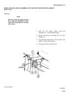
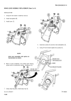
12. Position lever assembly (N) and two thrust washers
(P) in bracket (Q).
Aline holes in bracket (Q) with
holes in thrust washers (P) and lever assembly (N).
13. Install pin (R) through alined holes.
14. Install nut (S) on setscrew (T).
15. Start setscrew (T) into bracket (Q).
16. Aline groove in pin (R) with setscrew (T).
17. Using 1/4 inch wrench, tighten setscrew (T) to secure pin (R).
18. Using 7/16 inch wrench, tighten nut (S) against bracket (Q).
Go on to Sheet 10
TA146374
13-86
Back to Top


