TM-9-2350-260-20-1-3 - Page 621 of 783
TM 9-2350-260-20-1-3
BRAKE LEVER ASSEMBLY REPLACEMENT (Sheet 4 of 4)
8.
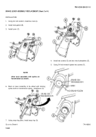
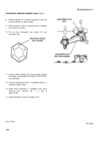
Aline holes in lever (F) with rod (H).
9.
Install pin (J).
10. Install nut (K) on screw (L).
11. Aline groove in pin (J) with hole for screw (L).
12. Using screwdriver, install screw (L).
13. Using 7/16 inch wrench, tighten nut (K).
14. Place gasket (M) and shield (N) on cover (C).
15. Aline holes thru shield (N), gasket (M), and cover
(E).
Put lever (H) through hole in shield (N).
16. Using screwdriver, Install ten new lockwashers (P)
and screws (Q) loosely.
17. Using screwdriver, tighten the screws (Q).
18. Install 2A powerplant (page 514) or 2D powerplant
(page 5-40).
End of Task
TA146381
13-93
Back to Top


