TM-9-2350-261-20-2 - Page 13 of 1008
COOLANT FLOW DIAGRAM
INITIAL SETUP:
Maintenance Level
Unit
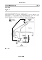
Engine coolant maintains normal operating temperatures. Coolant flow is as follows:
Coolant is drawn from the radiator by the coolant pump. It is pumped through the oil cooler, and the engine block, up to the
cylinder heads, and into the thermostat housing. The coolant then passes through a deaerator elbow and back to the radiator.
The deaerator elbow swirls the coolant to remove air. This air is vented back to the auxiliary tank.
The auxiliary tank provides for coolant overflow from the radiator. The tank also vents air out through its cap.
END OF TASK
0192 00-1/2 blank
0192 00
TM 9-2350-261-20-2
Back to Top

