TM-9-2350-261-20-4 - Page 385 of 767
TM 9-2350-261-20-4
R EPLAC E A C P OW ER EXTENS ION BOX A 7 (M1068 ON LY ) — Continued
0719 00
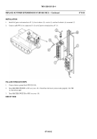
INSTALLATION
1 .
In stall A C pow er exten sion b ox A7 (3), fo ur w ash ers (5 ), screws (4), an d new lo cknu ts (6) o n mo unt (7).
2.
Connect cable W 8 (1) to connector J1 (2) on AC p ower extension box A7 (3).
FOLLOW-THROUGH STEPS
1.
Connect battery ground lead (WP 0294 00).
2.
Turn MASTER SWITCH to ON (see your -10). Check that electrical system works properly. See TM
11-7010-256-12&P.
3.
Turn MASTER SWITCH to OFF (see your -10).
END OF TASK
0719 00-2
Back to Top


