TM-9-2350-261-20-4 - Page 430 of 767
TM 9-2350-261-20-4
REPLACE POWER CONTROL ENCLOSURE CIRCUIT 44A
LEAD (M1068 ONLY)
0732 00
THIS WORK PACKAGE COVERS:
Removal (page 0732 00-1).
Installation (page 0732 00-2).
INITIAL SETUP:
Maintenance Level
Unit
Tools and Special Tools
General Mechanic’s Tool Kit (WP 0780 00, Item 29)
Materials/Parts
Locknut (4)
Lockwasher (10)
Tie strap (AR)
Personnel Required
Power-Generation Equipment Repairer 52D10
Equipment Condition
Engine stopped (see your -10)
Carrier blocked (see your -10)
All external power disconnected (TM 11-7010-256-
12&P)
Battery ground lead disconnected (WP 0294 00)
REMOVAL
1.
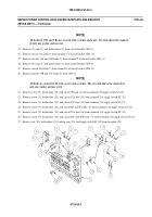
Remove ten screws (1) and lockwashers (2), and lower faceplate (3). Discard lockwashers.
2.
Remove nut (4), lockwasher (5), and lead 44A (6) from terminal X1 of relay K6 (7). Do not discard lockwasher.
3.
Remove tie straps (8) holding lead 44A (6) to other leads. Discard tie straps.
4.
Disconnect cable plug W38 P7 (9) from power control enclosure jack J28 (10).
5.
Remove four screws (11), locknuts (12), and connector J28 (10) with lead 44A (6) from power control enclosure (13).
Discard locknuts.
073200-1
Back to Top

