TM-9-2350-261-34 - Page 601 of 785
TM 9-2350-261-34
REPAIR EXTERNAL COMMUNICATION BOX A11 (M1068 ONLY) — Continued
0078 00
DISASSEMBLY
1.
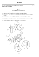
Remove four screws (13), locknuts (14), and two latches (15) from communication box (2). Discard locknuts.
2.
Remove four screws (13), locknuts (14), and two catches (12) from communication box lid (1). Discard locknuts.
3.
Remove four screws (10), locknuts (11), and latch half (9) from lid (1). Discard locknuts.
4.
Remove four screws (7), locknuts (8), and latch half (6) from communication box (2). Discard locknuts.
5.
Remove two screws (3), four washers (4), two locknuts (5), and lid (1) from communication box (2). Discard locknuts.
NOTE
See wiring diagram (page 0078 00-6) for assembly/disassembly of wires to connectors.
Tag leads/cables before removing/disconnecting. Replace pads only if damaged.
0078 00-2
Back to Top


