TM-9-2350-275-BD - Page 164 of 223
TM 9-2350-275-BD
COMMUNICATIONS SYSTEM
NOTES (Cont):
NOTE #6
NOTE #7
NOTE #8
NOTE #9
A
B
C
D
E
F
G
H
I
J
K
L
11-58
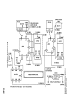
Ensure the connector comparability. If the older type CVC helmet
is substituted for the DH-132 series helmet then the cord assembly
CX-8650 B/GR must also be exchanged with the CVC-helmet.
This exchange will remove the capability to key the intercom or radio
by any means other than by the switch located on the CVC helmet.
If the mount is from any vehicle other than a vehicle with the
AN-VIC-1 intercom then the “Pivot terminal link" must be in position
as shown. .
If the R/T or aux receiver is from a vehicle not utilizing speech
security equipment then the X-mode position switch may have to be
changed. Turn your R/T ON and see below procedures.
Set the R/T SQUELCH control on OLD ON.
Remove the cover from the X-MODE receptacle, if the CALL light comes
on, the switch is in X-MODE, BUT if the CALL light does not come on, the
switch is in NORMAL. Organizational or higher maintenance should then:
Remove R/T from ount, turn R/T upside down.
Remove bottom cover from R/T.
Loosen assembly A 4000 captive screws.
Raise assembly A 4000 and lock brace.
Turn X-MODE-NORMAL switch to X-MODE.
Be sure leaf springs are equally curved.
Lower assembly A 4000 and tighten captive screws.
Be sure assembly hinge pin is pushed all the way in.
Replace bottom cover of R/T.
Replace R/T on to mount.
Back to Top


