TM-9-2350-275-BD - Page 165 of 223
TM 9-235-275-BD
COMMUNICATIONS SYSTEM
NOTE (Cont
If the AUX receiver is to be used in the X-MODE communications hookup, it
must be opened up and its switch set to X-MODE.
The AUX receiver switch must be placed in NORMAL after you are through with
the X-MODE hook-up.
NOTE #10 -
Loss of automatic channel selection if RT-246 is being used.
Section V. Common Vehicle Cording Diagrams
11-36. GENERAL.
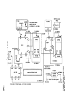
Cording diagrams for common U.S.
vehicles on the battlefield have been
provided in this section to aid in identifying components and cables that are
interchangeable.
These diagrams also assist in identifying cables without having to
trace them throughout the vehicle.
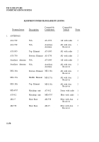
Cording Diagram For:
KY-57 General Configuration (Unclassified)
AN/VIC-l and AN/VRC-12 in M 1 Tank
AN/VRC-46, AN/VRC-64, or two AN/GRC-160’s with AN/VIC-1 in
M2 (chassis)
AN/VRC-46, AN/VRC-64 or (two) AN/GRC-160’s with AN/VIC-1,
in M3 (chassis)
AN/VRC-46, AN/VRC-64 or (two) AN/GRC-160’s with AN/VIC-1,
in M2 and M3 (turret)
AN/VIC-l and AN/VRC-12 in M60A1 Tank
AN/VRC-46, AN/VRC-64, or AN/GRC-160 with AN/VIC-l in M88A1
AN/VRC-46, AN/VRC-53, AN/GRC-125, AN/VRC-64, or AN/GRC-160
and AN/VIC-1 in M578
AN/VIC-l in M 113 and M577
AN/VRC-12 in M 113 Family
AN/GRC-160 and AN/VIC-1 in Improved Tow Vehicle M901
Page
11-61
11-62
11-63
11-63
11-64
11-65
11-66
11-67
11-68
11-68
11-69
11-59
Back to Top


