TM-9-2350-277-10 - Page 187 of 889
TM 9-2350-277-10
DESCRIPTION AND USE OF OPERATOR’S CONTROLS AND INDICATORS — Continued
0004 00
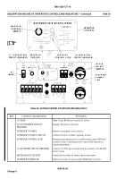
Table 39. OUTBACK MODEL FACEPLATE (M1068A3 ONLY)
KEY
CONTROL OR INDICATOR
FUNCTION
AC MAIN
Main Circuit Breaker for external AC power.
DC TO INVERTER CIRCUIT
BREAKER
Engages DC power to Inverters.
INVERTER CONTROL
Remote control plate to the inverters.
INVERTER CONTROL SWITCH
Controls inverters A and B as primary inverter.
INVERTER CONTROL LEDS
During normal operations the A and B inverter control LED will
remain on solid. A flashing inverter control LED indicates an
operational problem.
AC INVERTER CIRCUIT BREAKER
Controls 110 VAC power output from the inverters to the M1068
power system.
METER SELECT SWITCH
Switch between Main AC power and Inverter power.
INVERTER POWER LED
Indicates inverters are powering the M1068 power system.
0004 00-48
Change 5
Back to Top

