TM-9-2350-277-10 - Page 728 of 889
TM 9-2350-277-10
ASSEMBLE T130 TRACK SHOE SECTIONS OFF VEHICLE
0094 01
THIS WORK PACKAGE COVERS:
Assembly (page 0094 01-1).
INITIAL SETUP:
Maintenance Level
Operator
Tools and Special Tools
C row bar ( WP 0 102 0 0, Table
2
, Item 13)
D rive Pin Pu nch (W P 01 02 00 , Tab le
2
, Item 4 4)
G rease G un (WP 010 2 00, Table
2
, Item
25
)
Hamm er, 2 lb (W P 0102 00, Table
2
, Item 26)
Industrial Goggles (WP 0103 00)
A djustable Wr ench, 1-5/16
i
nch ( WP 0102 00, Table
2,
Item 64)
Socket Wrench, 11/16 inch (WP 0 102 00, Table
2
,
Item 49)
Track Fixture (WP 0 102 00, Table
2
, Item 23)
Wr ench Handle (WP 0 102 00, Table
2
, Item 30)
Personnel Required
Driver
Helper (H)
Equipment Condition
Track on level surface
ASSEMBLY
NOTE
Track shoe sections may come in 7 or 8 shoes per section. Make sure to count the number of
shoes during assembly. For all M113A3 FOV there are 63 track shoes required for the left
side and 64 track shoes required for the right side. Inspect each track shoe to see if anything
is wrong before it is assembled.
1.
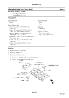
Match two sections of track. Have helper assist.
2.
Remove nut from track pin. Use 1/2 inch drive socket handle and 11/16 inch socket.
009401-1
Change 4
Back to Top


