TM-9-2350-277-20-1 - Page 368 of 855
TM 9-2350-277-20-1
TRANSMISSION DOES NOT DOWNSHIFT IN 1-4 POSITION
0066 00
INITIAL SETUP:
Maintenance Level
Unit
Tools and Special Tools
General Mechanic’s Tool Kit (WP 0926 00, Item 65)
Pressure Gauge Kit (WP 0926 00, Item 35)
Personnel Required
Mechanic
References
TM 9-2350-277-10
Equipment Condition
Engine stopped (TM 9-2350-277-10)
Carrier blocked (TM 9-2350-277-10)
Power plant access door open (TM 9-2350-277-10)
Driver’s power plant access panel removed
(WP 0441 00)
Power plant rear access panels removed (WP 0439 00)
Transmission in SL position
NOTE
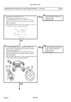
Pressure tester must read 4 psi. Any other reading indicates a fault.
T
1.
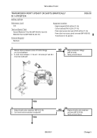
Remove plug (1) from GOVERNOR TWO (G2) port (2).
2.
Install 1/16 inch pressure tester adapter in G2 port (2).
3.
Install pressure tester on pressure tester adapter.
4.
Start engine and let idle. See TM 9-2350-277-10.
5.
Does pressure tester read more than 4 psi?
TN
1.
Faulty transmission beyond unit
maintenance repair.
2.
Notify supervisor.
Y
1.
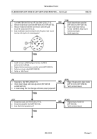
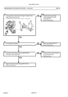
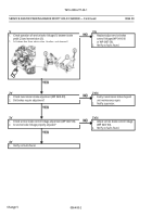
Has governor assembly been replaced?
YN
1.
Replace governor assembly
(WP 0397 00).
2.
Verify no faults found.
2Y
1.
Faulty transmission beyond unit maintenance repair.
2.
Notify supervisor.
Change 5
00
66
00-1/2 blank
Back to Top


