TM-9-2350-277-20-1 - Page 599 of 855
TM 9-2350-277-20-1
PHONE EXTENSION BOX A14 POST(S) INOPERATIVE (M1068A3 ONLY)—Continued
0114 00
T
1.
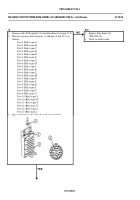
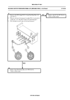
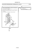
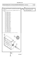
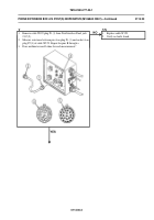
Remove cable W129 plug P2 (1) from Phone Extension Box A14
jack J1 (2).
2.
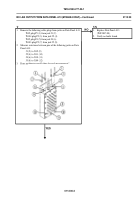
Measure resistance between posts (3) and pins of jack J1 (2) as
follows:
Post 1 (Blk) to pin A
Post 1 (Red) to pin B
Post 2 (Blk) to pin C
Post 2 (Red) to pin D
Post 3 (Blk) to pin E
Post 3 (Red) to pin F
Post 4 (Blk) to pin G
Post 4 (Red) to pin H
Post 5 (Blk) to pin J
Post 5 (Red) to pin K
Post 6 (Blk) to pin L
Post 6 (Red) to pin M
Post 7 (Blk) to pin N
Post 7 (Red) to pin P
Post 8 (Blk) to pin R
Post 8 (Red) to pin S
Post 9 (Blk) to pin T
Post 9 (Red) to pin U
Post 10 (Blk) to pin V
Post 10 (Red) to pin W
Post 11 (Blk) to pin X
Post 11 (Red) to pin Y
Post 12 (Blk) to pin Z
Post 12 (Red) to pin a
3.
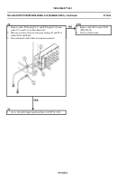
Does multimeter read 0 ohms for each measurement?
YES
NO
TN
1.
Replace Phone Extension Box A14.
See TM 11-7010-256-12&P.
2.
Verify no faults found.
0114 00-2
Back to Top


