TM-9-2350-277-20-2 - Page 284 of 783
TM 9-2350-277-20-2
REPLACE EXTERNAL FUEL TANKS (ALL EXCEPT M577A3 AND M1068A3) — Continued
0179 00
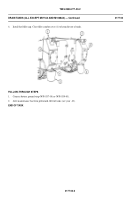
5.
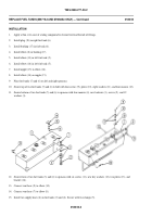
Apply caulking compound to space around installed screw heads (1) and washers (2) on rear hull plate. Do not apply
compound to screw threads which engage with fuel tank (3).
0179 00-6
Change 3
NOTE
Inside of mounting holes and full diameter area under each washer must be free of paint to
ensure good electrical ground.
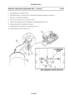
4.
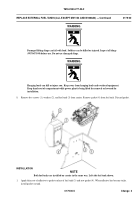
Check that mounting holes and surfaces are free of paint. Secure fuel tank (3) to rear hull plate with five screws (1) and
washers (2). TIGHTEN SCREWS TO 270-295 LB-FT (366-400 N
m) TORQUE. Remove lifting device. Have helper
assist.
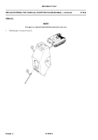
3.
Apply grease GMD to threads of five screws (1).
2.
Attach lifting device to lifting bracket (5). Position fuel tank (3) against rear hull plate. Have helper assist.
Damaged lifting slings can fail with load. Soldiers can be killed or injured. Inspect all slings
(WP 0673 00) before use. Do not use damaged slings.
WARNING
Hanging loads can kill or injure you. Keep away from hanging loads and overhead equipment.
Keep hands out of compartment while power plant is being lifted for removal or lowered for
installation.
WARNING
Back to Top

