TM-9-2350-277-20-3 - Page 329 of 941
TM 9-2350-277-20-3
REPLACE STOP SWITCH — Continued
0332 00
2.
Check circuit 75A lead and circuit 75B lead for continuity with switch plunger depressed. If test indicates open circuit,
replace defective switch.
3.
Check circuit 366 lead and circuit 366A lead for continuity with switch plunger released. If test indicates open circuit,
replace defective switch.
INSTALLATION
1.
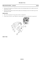
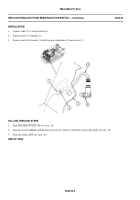
Place switch (5) on bracket (8). Secure with two washers (7) and jamnut (6).
2.
Connect circuit 75A lead (1), circuit 75B lead (2), circuit 366 lead (3), and circuit 366A lead (4) to stop switch (5).
END OF TASK
0332 00-2
Back to Top


