TM-9-2350-277-20-4 - Page 32 of 861
TM 9-2350-277-20-4
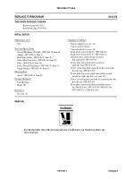
REPLACE TORSION BAR ANCHOR
0414 00
THIS WORK PACKAGE COVERS:
Removal (page 0414 00-1).
Installation (page 0414 00-3).
INITIAL SETUP:
Maintenance Level
Unit
Tools and Special Tools
General Mechanic’s Tool Kit (WP 0926 00, Item 65)
Socket Wrench Set (Required for M1064A3 5th anchor
only) (WP 0926 00, Item 73)
Torque Wrench (Required for M1064A3 5th anchor
only) (WP 0926 00, Item 86)
Materials/Parts
Cotter pin (2)
Preformed packing (Required for 3rd, 4th, & 5th anchors
only)
Personnel Required
Unit Mechanic
References
See your -10
Equipment Condition
Carrier on level surface
Engine stopped (see your -10)
Carrier blocked (see your -10)
Road wheel removed (T130) (WP 0426 00)
Torsion bar removed (WP 0413 00)
Power plant removed (Required for 2nd right anchor
only) (WP 0156 00)
REMOVAL
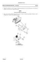
NOTE
The 5th anchor on the M1064A3 carrier is secured with screws instead of pins because it is
located under the welded floor plates next to the mortar turntable.
NOTE
On all carriers, preformed packings are located behind the 3rd, 4th, and 5th anchors only.
0414 00-1
Road wheel removed (T150) (WP 0426 01)
Change 3
Back to Top

