TM-9-2350-277-34 - Page 190 of 871
TM 9-2350-277-34
REPAIR/REPLACE ACCELERATOR STOP SUPPORT ASSEMBLY
0018 00
THIS WORK PACKAGE COVERS:
Removal (page 0018 00-1).
Installation (page 0018 00-2).
INITIAL SETUP:
Maintenance Level
Direct Support
Tools and Special Tools
Metal Worker’s Tool Kit (WP 0120 00, Item 63)
Trailer Mounted Welding Shop (WP 0120 00, Item 69)
Sander Spindle Adapter (WP 0120 00, Item 1)
Welder’s Gloves (WP 0120 00, Item 18)
Industrial Goggles (WP 0120 00, Item 19)
Welder’s Helmet (WP 0120 00, Item 21)
Electric Disc Sander (WP 0120 00, Item 46)
Arc Welding Machine (WP 0120 00, Item 68)
Materials/Parts
Welding electrode (WP 0122 00, Item 35)
Personnel Required
Metal Worker 44B10
References
See your -10
See your -20
TM 9-237
TM 43-0139
Equipment Condition
Engine stopped (see your -10)
Carrier blocked (see your -10)
Ramp lowered (see your -10)
Battery ground strap disconnected (see your -20)
Driver’s seat removed (see your -20)
Upper accelerator pedal removed (see your -20)
Lower accelerator pedal removed (see your -20)
Upper and lower service brake pedals removed
(see your -20)
REMOVAL
1.
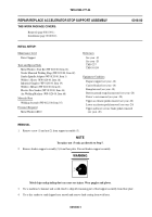
Remove screw (1) and nut (2) from support assembly (3).
NOTE
To replace nut (5) only, go directly to Step 5.
2.
Remove broken support assembly (3) from floor plate. Discard broken support assembly.
WARNING
Metal chips and grinding dust can cause eye injury. Wear goggles and gloves.
3.
Use a machinist’s hammer and a cold chisel to chip off remaining part of bad support assembly from floor plate.
4.
Use a disc sander to sand chipped area smooth and remove hard coating from weld area.
0018 00-1
Back to Top


