TM-9-2350-277-34 - Page 748 of 871
TM 9-2350-277-34
REPLACE LAN A CABLE W101 AND/OR LAN B CABLE W102 (M1068A3
ONLY)
0105 00
THIS WORK PACKAGE COVERS:
Removal (page 0105 00-1).
Installation (page 0105 00-3).
INITIAL SETUP:
Maintenance Level
Direct Support
Tools and Special Tools
Electronic Equipment Tool Kit (WP 0120 00, Item 61)
Materials/Parts
Locknut (2)
Lock washer (14)
Strap
Personnel Required
Radio Repairer 29E10
Helper (H)
References
See your -10
See your -20
TM 11-7010-256-12&P
Equipment Condition
Engine stopped (see your -10)
Carrier blocked (see your -10)
All external power disconnected
(TM 11-7010-256-12&P)
Battery ground strap disconnected (see your -20)
REMOVAL
1.
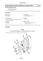
Lift and secure cover (1) of external communications box A11 (2).
2.
Remove fourteen screws (3), Lock washers (4), and faceplate (5) from external communications box A11 (2). Discard
Lock washers.
NOTE
Tag cables before disconnecting them.
3.
Disconnect cable W101, jack J103 (6), jamnut (7), inside bushing (8) and outside bushing (9) from faceplate LAN A (10)
on external communications box A11 (2).
4.
Disconnect cable W102, jack J104 (11) jamnut (7), inside bushing (8) and outside bushing (9) from faceplate LAN B
(12) on external communications box A11 (2).
0105 00-1
Back to Top


