TM-9-2350-311-10 - Page 484 of 775
TM 9--2350--311--10
3--80
Change 6
3--6
ARMAMENT AND CAB MAINTENANCE — CONTINUED
3--6.8
Breech Mechanism — Continued
c. Assembly — Continued
(f)
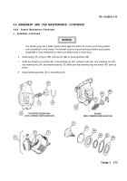
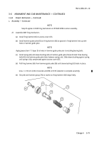
Assemble two grooved pins (59) and two retaining rings (58) in case (60), if disassembled.
(g)
Install two springs (62 and 61) over hammer guide yoke (56).
(h)
Install assembled case (60) over springs (62 and 61).
(i)
Install follower (53) over assembled case (60) alining pins with cutouts of follower.
(j)
Using M34 or M18 fuzesetter, compress two springs (62 and 61) and follower (53) over hammer
guide yoke (56) until manual control lever (55) can be inserted into hammer guide yoke.
(k)
Install grooved pin (54) in manual control lever (55) and hammer guide yoke (56).
(l)
Depress firing hammer (66) against solid flat surface to seat firing mechanism (2).
26
With firing group block (1) in center position, insert firing mechanism (2) and rotate counterclockwise.
59
58
60
61
62
56
53
54
2
1
55
66
Back to Top


