TM-9-2350-311-10 - Page 488 of 775
TM 9-2350-311-10
3-7 FIRE CONTROL ALINEMENT TESTS AND MEASUREMENTS - CONTINUED
3-7.2
M1A1 Gunner’s Quadrant Tests - Continued
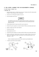
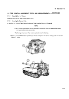
b. End-For-End Test
1
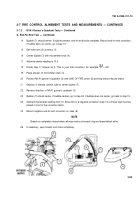
Inspect the elevation seats (1) on breech ring for dirt or burrs. If necessary, clean with a wiping rag (item
35, Appx D). If burrs are present, notify unit maintenance.
2
Set index arm (2) and micrometer knob (4) of Ml Al gunner’s quadrant (3) at zero.
The breechblock must be slightly open and the operating handle left unlocked. To prevent injury
to personnel, be careful not to lift up on operating cam before securing operating handle after
leveling cannon tube.
3
4
Unlatch operating handle (5) enough to place M1A1 gunner’s quadrant (3).
Position M1A1 gunner’s quadrant (3) on breech with LINE OF FIRE arrow (6) pointing toward muzzle
brake.
5
6
7
Depress or elevate cannon tube to center bubble
(7).
Reverse direction of Ml Al gunner’s quadrant (3).
Bubble (7) should center. If bubble centers, end-for-end test is complete. If bubble does not center, go to
step 8.
8
9
10
11
12
13
Center bubble (7) using micrometer knob (4). If bubble centers, go to step 9. If bubble does not center,
go to step 15.
Read the black figures. Divide micrometer reading by 2 to determine correction factor (Example: 0.4
2
= 0.2; so 0.2 is correction factor).
Place correction factor on micrometer knob (4).
Position M1A1 gunner’s quadrant (3) with LINE OF FIRE arrow (6) pointing toward muzzle brake.
Depress or elevate cannon tube to center bubble (7).
Reverse direction of Ml Al gunner’s quadrant (3).
NOTE
In tolerance is ± 0.4. Anything greater is not acceptable.
3-84
Change 2
Back to Top


