TM-9-2350-311-10 - Page 60 of 775
TM 9--2350--311--10
1--22
Change 5
1--13 EQUIPMENT DATA — CONTINUED
PRIMARY ARMAMENT (TWO CONFIGURATIONS)* — CONTINUED
Maximum range (M109A2/M109A3/M109A4)
(Zone 7) 14,600 m
.......................................
(Zone 8) 18,000 m
(Zone 8 with RAP) 23,500 m
Maximum Range (M109A5)
(Zone 5 MACS) 22,000 m
................................................
(Zone 5 MACS with RAP) 30,000 m
(Zone 7) 18,000 m
(Zone 8) 22,000 m
(Zone 8 with RAP) 30,000 m
Maximum rate of fire
4 rds/min for 3 min
............................................................
Sustained rate of fire
(Zones 1--7) 1 rd/min
..........................................................
(Zone 8) 1 rd/min for 60 min
1rdevery3m
intherea
fter
SECONDARY ARMAMENT
Machine gun
Caliber 50, M2, heavy barrel
..........................................................
* All data listed applies to both configurations unless specified otherwise.
Section III. PRINCIPLES OF OPERATION
1--14 EQUIPMENT OPERATION AND DESCRIPTION
1--14.1
Powerplant
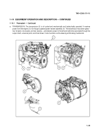
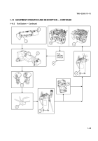
The flow diagram illustrates the transfer of power generated by the powerplant to the track assembly.
a. POWERPLANT. The powerplant (1) can be removed from the vehicle as a complete unitthat consistsof anengine
(Model 7083--7396) (2) or LHR engine (Model 7083--7391) (3), transfer assembly (4), and transmission (5).
b. ENGINE (MODEL 7083--7396). Engine (Model 7083--7396) (2) is a liquid-cooled, two-stroke cycle, diesel-type,
model 8V71T equipped with an exhaust-driven turbocharger (6). The engine develops 405 horsepower at 2300
rpm and delivers power to the transfer assembly (4).
c.
LHR ENGINE (MODEL 7083--7391). LHR Engine (Model 7083--7391) (3) is a liquid-cooled, two-stroke cycle, low
heat rejection, diesel-type, model 8V71T equipped with an exhaust-driven turbocharger (6). The engine develops
440 horsepower at 2300 rpm, delivers power to the transfer assembly (4), and uses glow plugs (7).
d. TRANSFER ASSEMBLY. The transfer assembly (4) receives power from the engine (2 or 3) and transfers that
power to the transmission (5).
Back to Top

